中文
中文 English
 Español
 Français
- (1) Main technical parameters
(1) Main technical parameters
Pilot oil circuit working pressure (adjusted by the control oil circuit relief valve): 2.5MPa
Theoretical displacement:125mL/r
Nominal flow (Refers to the steering wheel 60r/min ): 7.5L/min
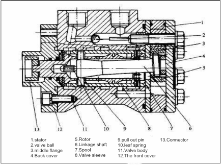
- (2) Main structure and working principle
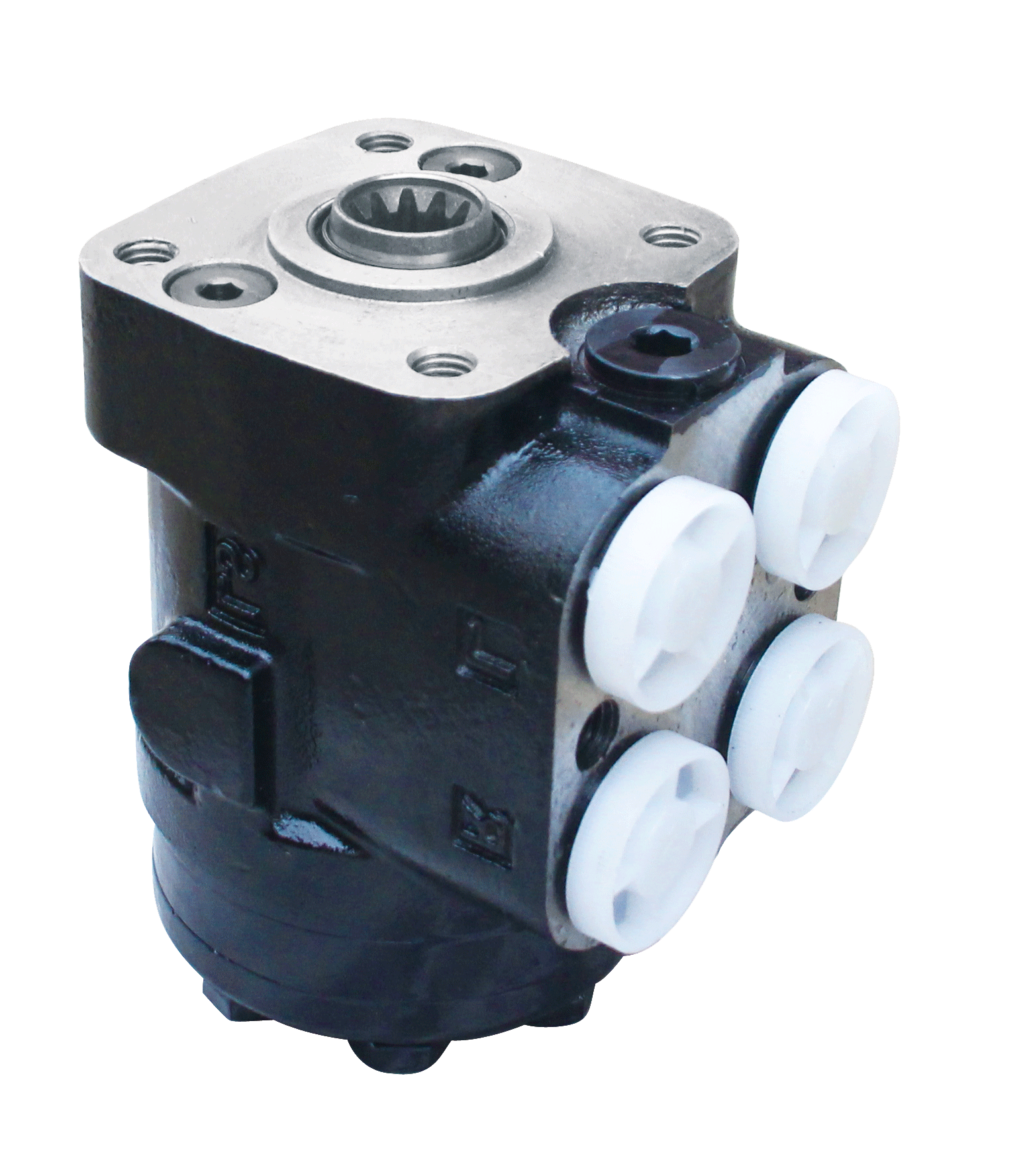
The full hydraulic steering unit is mainly composed of a follow-up rotary valve and a metering motor.
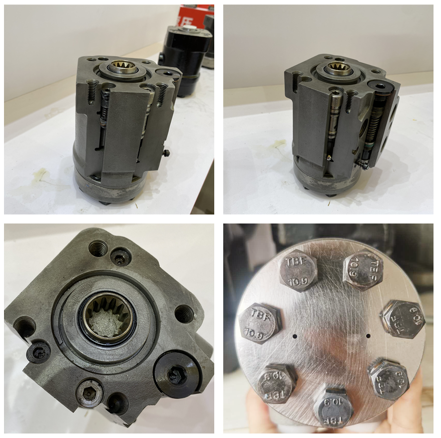
The follow-up rotary valve includes a spool, sleeve, and a valve body to control the direction of oil flow. The stator and rotor realize the function of metering the motor to ensure that the oil output is proportional to the steering wheel angle. Turn the steering wheel, when oil passes through the metering motor, the valve sleeve and the valve core are driven to rotate in the same direction through the rotor, the linkage shaft, and the pin, and the oil is sent to the pilot oil inlet and outlet of the flow amplifying valve to control the main valve of the flow amplifying valve The core action, the oil volume is enlarged. So as to control the steering.
PIC:M+S
When the follower valve is in the middle position (that is, the steering wheel is not moving), the oil discharged by the pilot pump is returned to the oil tank through the control oil circuit overflow valve. When the steering wheel is turned, the oil from the pilot pump is sent to the metering motor via the follow-up rotary valve. Push the rotor to rotate synchronously with the steering wheel, and send the pilot oil to one end of the valve stem of the flow amplifying valve. Make its valve stem move to realize steering. The oil at the other end of the valve stem is returned to the oil tank through the follow-up rotary valve. When the steering wheel turns faster, there is more pilot oil from the metering motor to the end of the flow amplifying valve stem, and the displacement of the valve stem increases, and the steering is faster. The steering wheel and the valve core are connected together.
When the steering wheel rotates, the valve core rotates through a small angle until the spring plate is pressed, and the valve sleeve rotates. At this time, the valve core and the valve sleeve are separated by an angle to connect the oil circuit. At the same time, the linkage shaft connected with the valve sleeve rotates together to drive the rotation of the rotor in the stator to send the pilot oil proportional to the steering wheel angle to the flow amplifying valve. The steering wheel stops rotating the spring leaf so that the valve sleeve and the valve core return to the middle position, closing the oil circuit.
- (3) product analysis
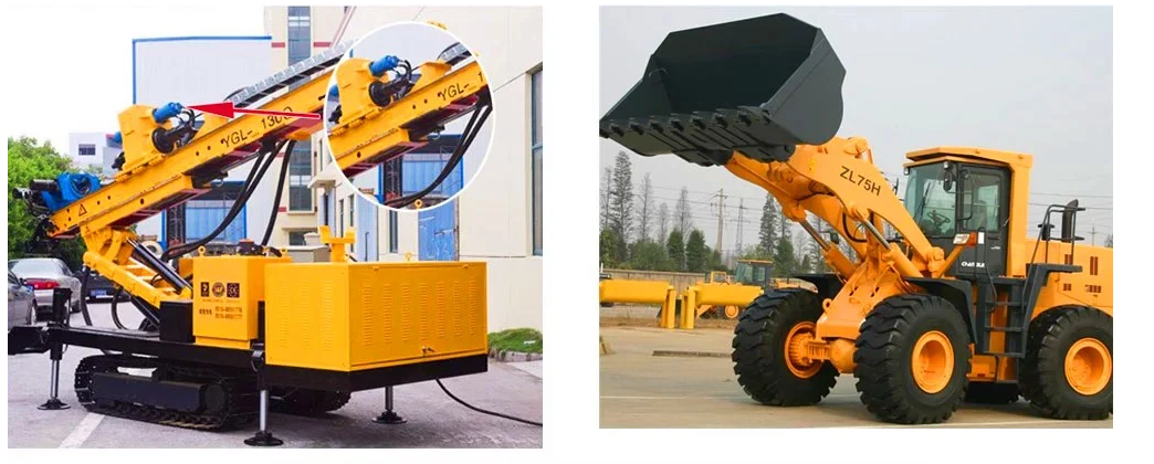
With the rapid development of my country's economy, the market demand for hydraulic steering unit 101S, OMPS series clutches have a very wide range of applications, and get good reputation from customers. Our company's production plan is flexible. In addition to accepting large quantities of product orders, it can also be adjusted according to customer needs to meet more and more available needs.
Parts drawing
Generally, each part should have its own part drawing, and indicate the detailed size, processing symbol, tolerance accuracy requirement, material, weight, etc. on the drawing. For standard parts , such as screws, nuts, washers, etc., parts drawings can be omitted. If a part is a standard product manufactured by another factory, this kind of drawing can be omitted, and only the technical specifications need to be listed. The structure diagram and assembly diagram are as follows: