中文
中文 English
 Español
 Français
{{i.title_en}}
Home
> Hydraulics> Hydraulic Pump> Piston Pump > Axial Piston-bent Axis Design Variable Displacement Pump A7V
Axial Piston-bent Axis Design Variable Displacement Pump A7V
MOQ: 100 PCS
Note: If you have any questions,please contact us
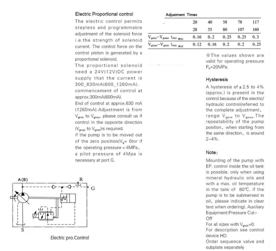
- 1.Variable displacement pump, axial piston, bent axis design, for hydrostatic transmissions in open circuits.
- 2.The flow if proportional to the drive speed and the displacement and is steplessly variable at constant drive speed.
- 3.Comprehensive programme of control devices for every control and regulation function.
- 4.Operation of both mineral, and fire-resistant fluids
- A7V
BEIJING HUADE HYDRAULIC INDUSTRIAL GROUP CO.,LTD
Since:
1979
Product Description
| Beijing Huade Hydraulic Industrial Group Co.,ltd | Variable Displacement Pump A7V For open circuits ,axial tapered piston, bent axis design | RC92100/12.2004 | |
| Size 20-500 | Peak pressure up to 40MPa | ReplaceRC92100/09.2003 | |
Special Features
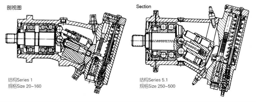
series 1
High performance rotary group with well-proven spherical control area offering the following advantages; self centering. low peripheral speed, high efficiency.
Long service life robust rolling bearing.
Drive shaft will support radial loads.
Low noise level.
High duty roller bearing for inter-mittent high pressure operation.
For continuous duty hydrostatic bearing are available.
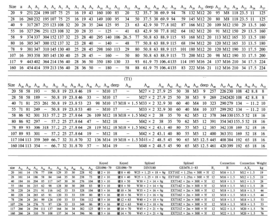
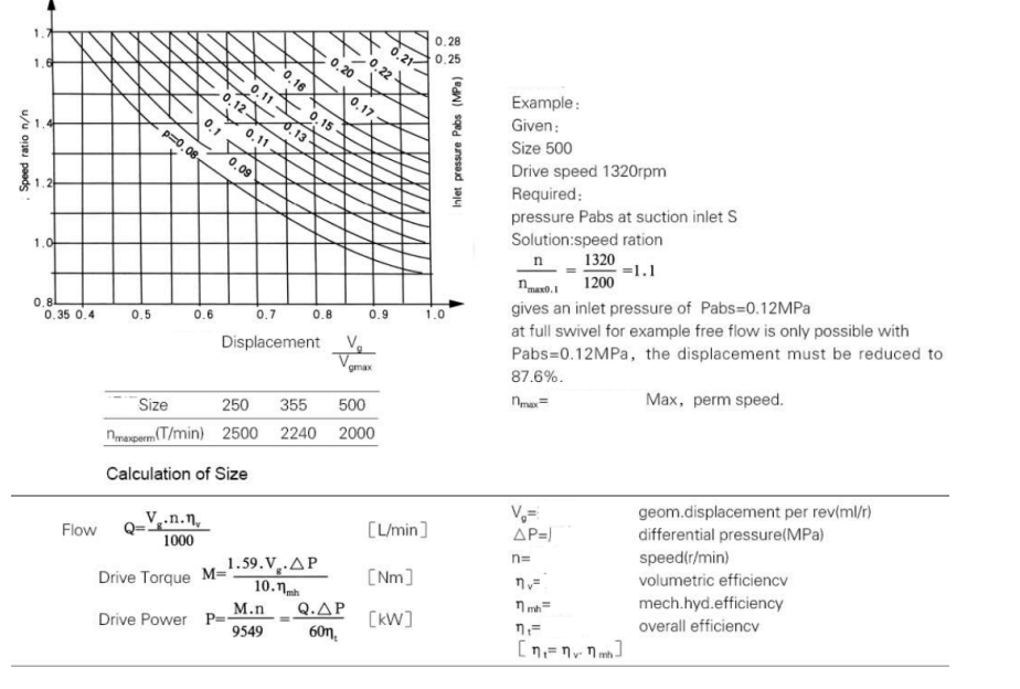
Technical data
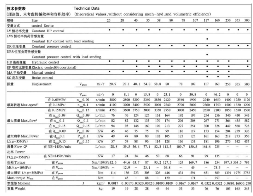
1) The values shown are valid for Vgmax.with an absolute pressure at suction inlet S and when operated on mineral oil.
2) Calculated with a volumetric efficiency of 97%.
3) The maximum speeds at 0.15MPa shown must not be exceeded, even with higher loading. On those sizes with Vgmin>o, however the maximum speeds can be increased to the values for those sizes with Vgmin>o, by reducing the displacement(Vg < Vgmax) maintaining max.flow.The relevant sizes are 28-20, 55-40, 80-85, 107-78, 160-117.
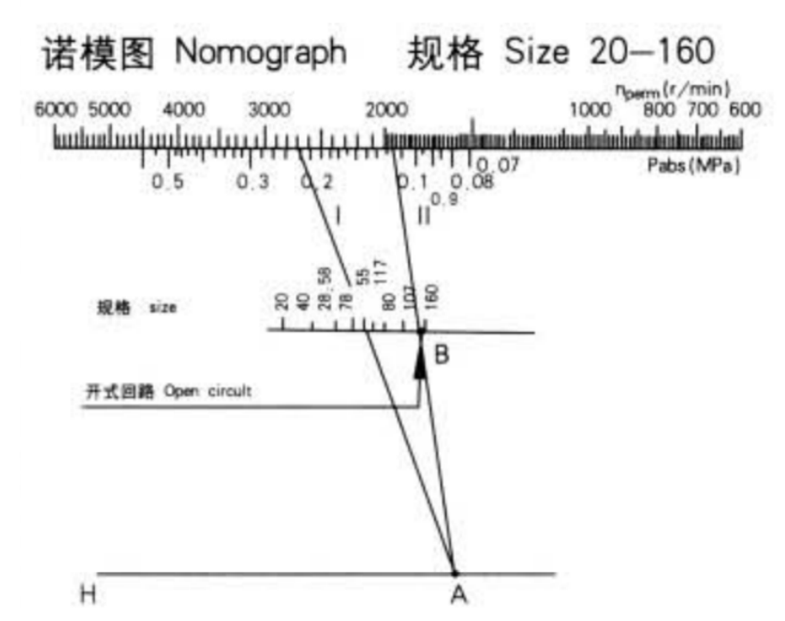
Permissible speed nperm and suction pressure Pabs can be read from the nommograph. However,the max, speeds(see table)and min.and max. suction pressure must be taken into account.
Example: Given: size 55D rive speed 2700r/min Required: pressure Pabs at the suction inlet.
Solution: Line 1 on scale nperm drawn towards size 55 crosses line hat port A. line 11 from point A to point B(open circuit) gives the result Pabs=0.117Mpa
Inlet Operation Pressure Absolute pressure at port S:
Pabs min----0.08MPa: Pabs max---0.2MPa
Operating Pressure Range-Outlet Side:
Nominal pressure --PN=35MPa: Peak pressure --Pmax=40MPa
Fluid Temperature Range:
P min-------0.25℃: P max----+80℃
Viscosity Range:
Vmin--10mm2/s; Vmax--(for short periods)10mm2/s
Optimum operating viscosity:Vopt--16-36mm2/s
Fluid recommendation; Operating recommended viscosity grade temperature to DIN 51519 range ISO (VG) at 40℃
| 40--50°C | VG32 • 32mm2/S |
| 50—60°C | VG46 • 46mm2/S |
| 60—70°C | VG68 • 68mm2/S |
| 70—80°C | VG100 - 100mm2/S |
Filtration of Hydraulic Fluid
Recommended filtration 10μm Coarser filtration of 25-40μm is possible, but longer component life, will be achieved using 10μm filtration due to lowest component wear.
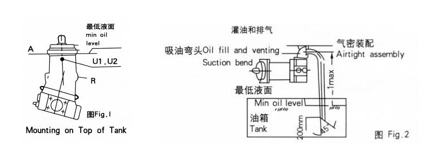
Mounting Position
Optional, The pump housing must always be filled with Oil.
When mounting Within a tank the plug must be removed form port R and This port must be at the top.90℃ pipe bend to be screwed in (noise reduction). Note:
Vertical mounting with drive shaft pointing upwards:for this case a model With port S U1 and U2 must be ordered (indicate in clear text: with ports U1and U2). The minimum oil level must not fall below the “A” line, as shown is Fig1.
when mounting outside a tank, the pump must be bled at port U1 or U2 prior to commissioning.
Mounting on Top of Tank Mounting of the A7V variable pump above tank must be considered as a special pump installation and should only be realized under specific conditions.
When ordering pumps for mounting on top of tank, state in clear text: "To Be Used for Above Tank Mounting°
This installation requires that the suction port be at the top and the suction pipe be kept as short as possible and the end of the pope be at least 200mm below minimum oil level, see Fig2.
The cross-cut of the suction pump should be so dimensioned to ensure that the flow velocity of the pressure fluid lies between 0.8 and 1m/s.
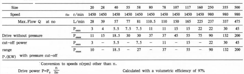
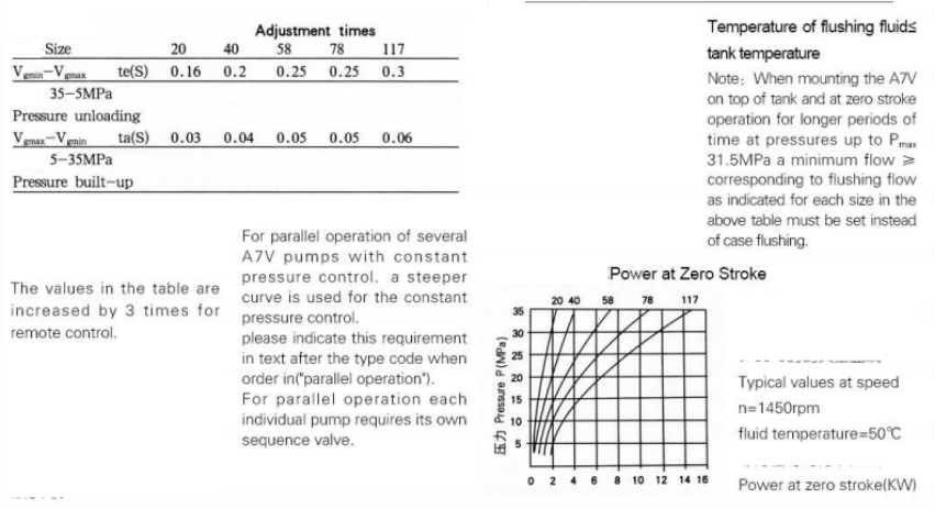
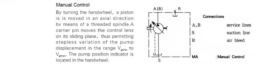
| Size | Max speed r/min | Max length of suction pipe Lmax(mm) | nmax(r/min) | nE= 1450( r/min) |
| 20 | 3610 | 600 | 41.8 | 26.5 |
| 28 | 2660 | 600 | 42 | 31 |
| 40 | 3040 | 750 | 53.6 | 37 |
| 55 | 2240 | 750 | 53.8 | 43.3 |
| 58 | 2700 | 750 | 61.3 | 45 |
| 80 | 2015 | 750 | 61.6 | 52.3 |
| 78 | 2410 | 750 | 66.6 | 51.6 |
| 107 | 1800 | 750 | 67.5 | 60.5 |
| 117 | 2125 | 850 | 76.6 | 63.3 |
| 160 | 1565 | 850 | 77 | 74 |
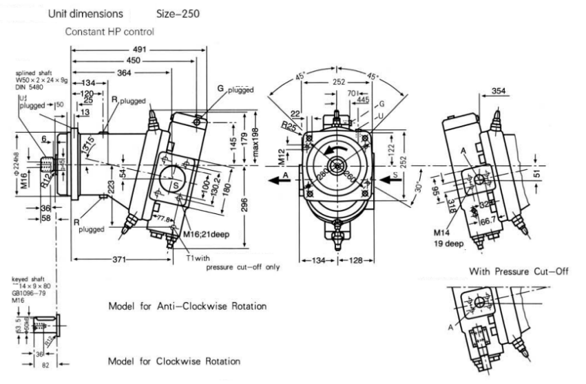
Size 250-500
Calculation of Inlet Pressure Pabs at Suction Inlet S and of Reduction in Displacement at Increased Speeds.
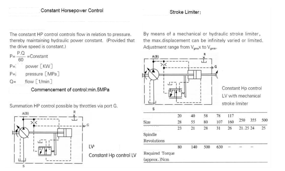
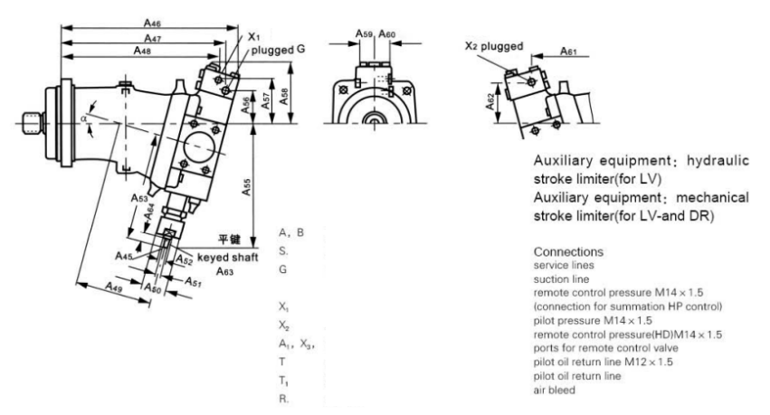
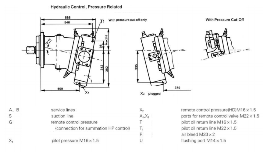
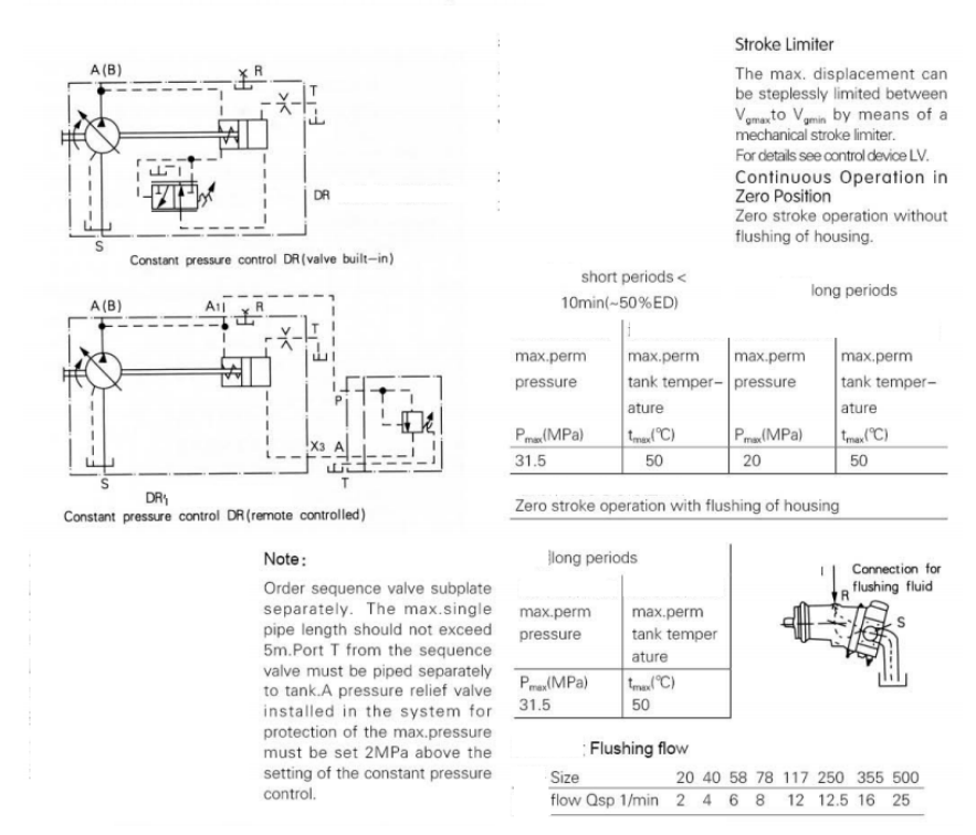
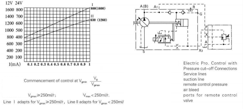
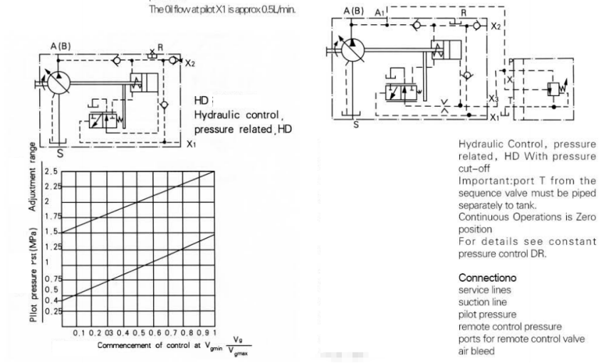
A Pilot pressure(port X1)of at least 10% of the operating pressure is required for the hydraulic stroke limiter Max. permissible pressure at port X1=20MPa(for all Sizes) if it is required to limit the flow at an operating pressure < 5MPa then a boost pressure of min 5MPa must be applied ax port X2(at port X1 then, mini O%=O.5MPa)
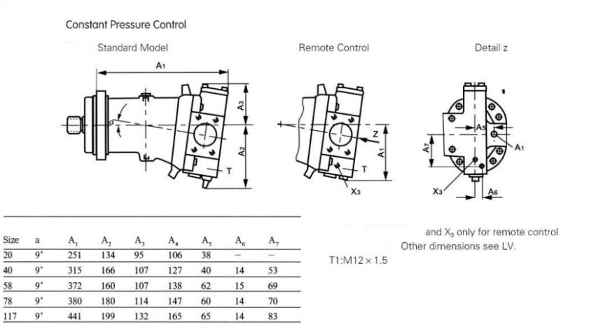
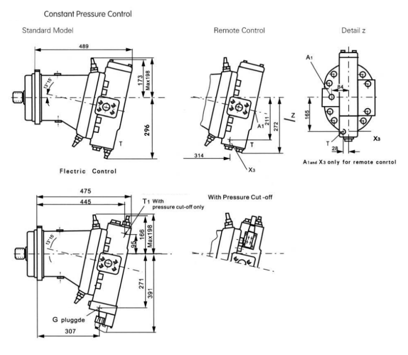
Constant HP control LV with hydraulic stroke limiter
For all sizes With Vgmin=0
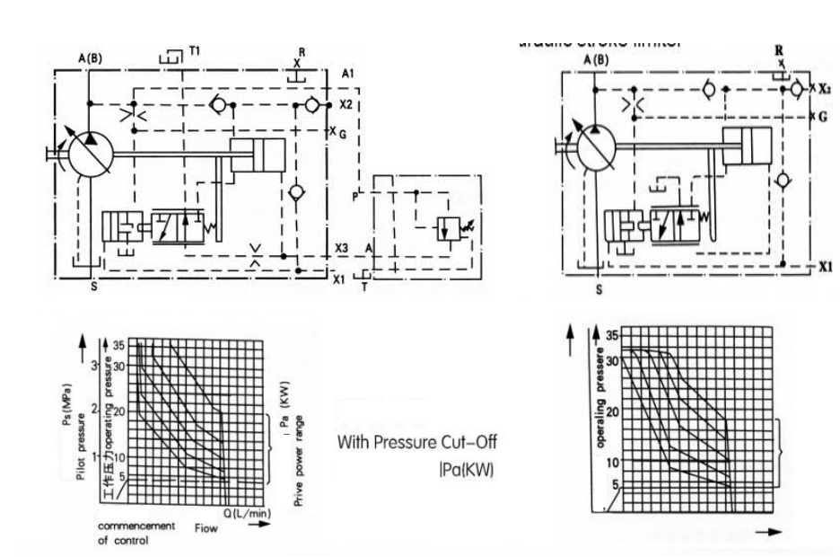
The pressure cut-off is a constant pressure control superposed on the constant HP control and is carried out by means of a sequence Valve. when the set. maximum pressure is reached adjustment range up to 315MPa), the Valve opens and the flow is automatically reduced to Q=0). The sequence valve is mounted separately from the pump in any suitable location one subplate(remote control).
The max./single pipe length must not exceed 5 m. order sequence valve and sub-plate separately.
When using the constant HP control with pressure cut off, the pump control times, will be approximately 3 times longer than those obtained with the constant pressure control DR. Important :Port T form the sequence valve and pilot Oil return line T1 must be piped direct to tank(cooler) Continuous
Operation in zero position see constant pressure control DR.
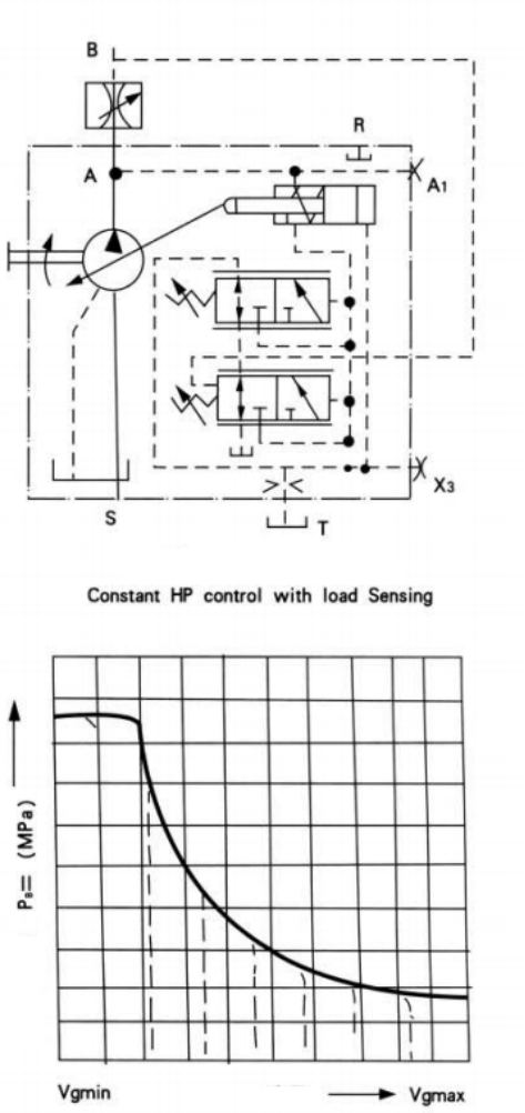
The load sensing Valve is a flow control valve which operates as function of the load pressure to regulate the pump displacement in order to match the requirement of the consumer unit.
The pump flow is influenced by the external orifice control black, throttle) fitted between pump and serviced unit, ber curve. The valve compares pressure before and after the orifice and maintains the pressure before and after the orifice and maintains the pressure drop (differential pressure APJacross the orifice-and therefore the pump flow-constant, if differential pressure AP increases, the pump is swelled back towards Vgrnin, and if AP decreases the pump is swelled out towards Vgmax, until a balance is restored Within the valve.
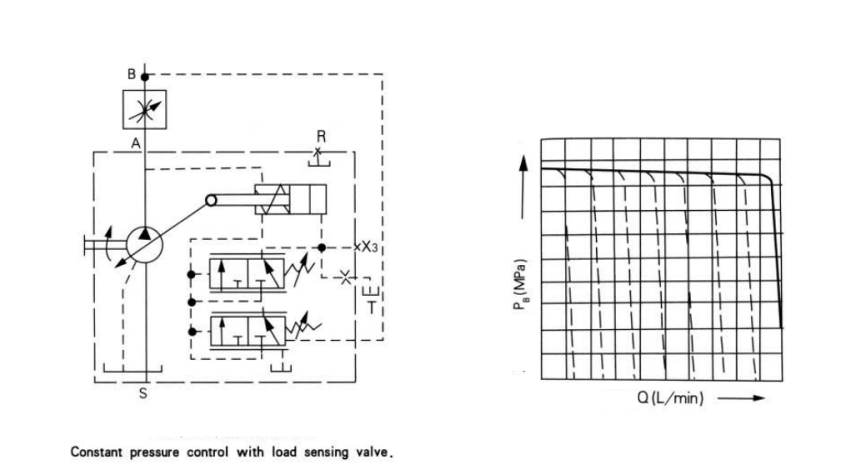
Variation: Constant Pressure control With Load sensing
The load sensing valve is a flow control valve which operates as function of the load pressure to regulate the pump displacement in order to match the requirement of the consumer unit. The pump flow is influenced by the external orifice(control black, throttle)fitted between pump and serviced unit, but is not affected by load pressure throughout the range below the power curve. The valve compares pressure before and after the orifice and maintains the pressure before and after The orifice and maintains the pressure drop (differential pressure AP) across the onfice-and therefore the pump flow-constant, if differential pressure AP increases, the pump is swivelled back towards Vgmirp and if AP decreases the pump is swivelled out towards Vgmax, until a balance is restored with in the valve.
AP=Ppump -Pserviced unit
P may be set with the range 14 bar to 25 bar. The
standard setting is 18 bar(please state required setting in clear text). The stand by pressure for zero stroke operation forifice closelis approx.2 bar above the AP setting. The constant pressure control is superimposed on the load sensing valve, i, e, the load sensing function operates below the set pressure. The orifice is not included in the standard supply.
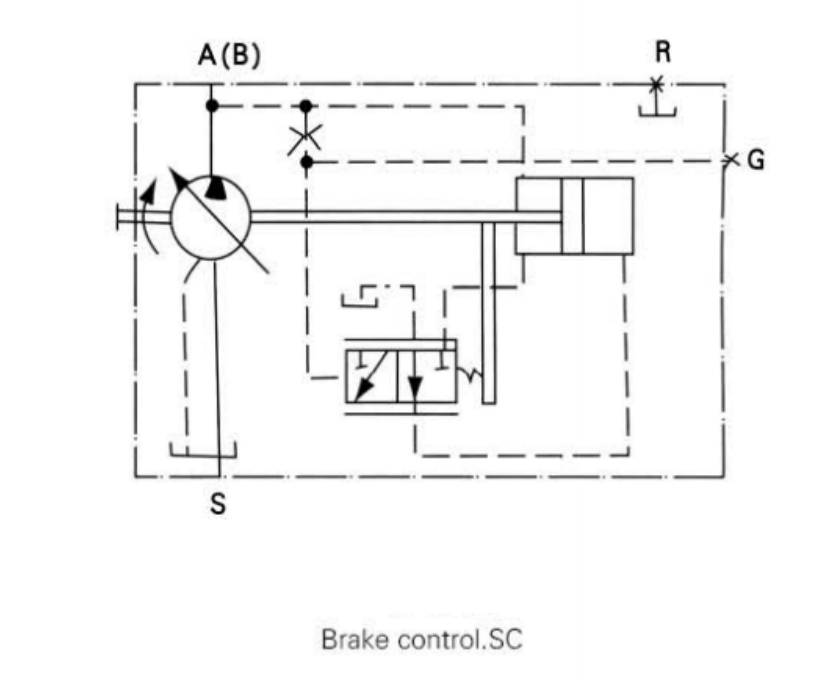
Brake control
When operation pressure goes up to the setting pressure, the flow is max,and the torque is max
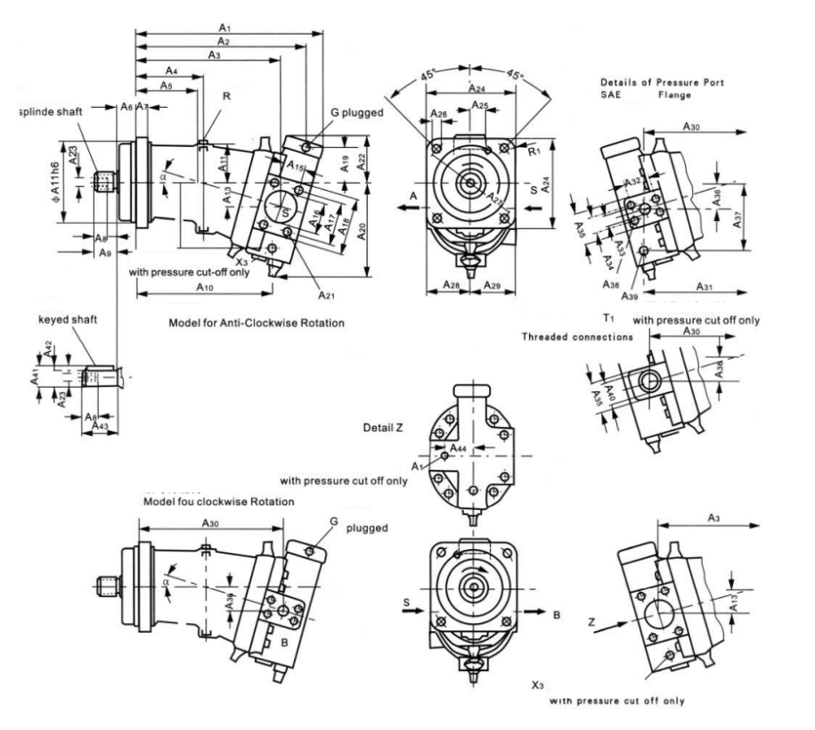
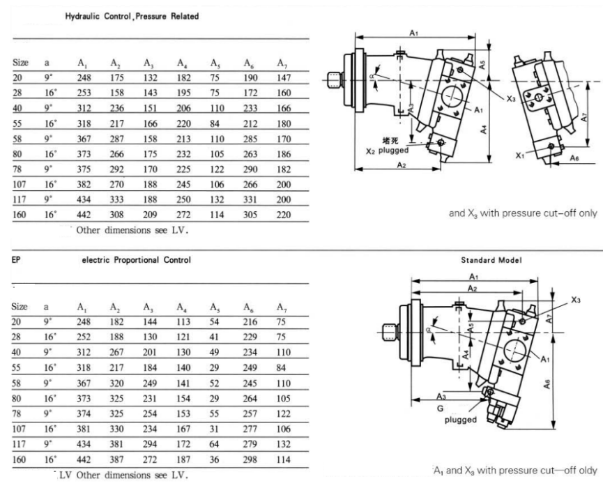
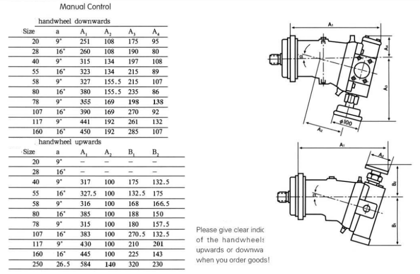
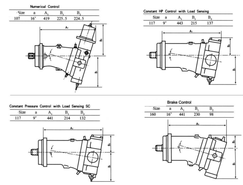
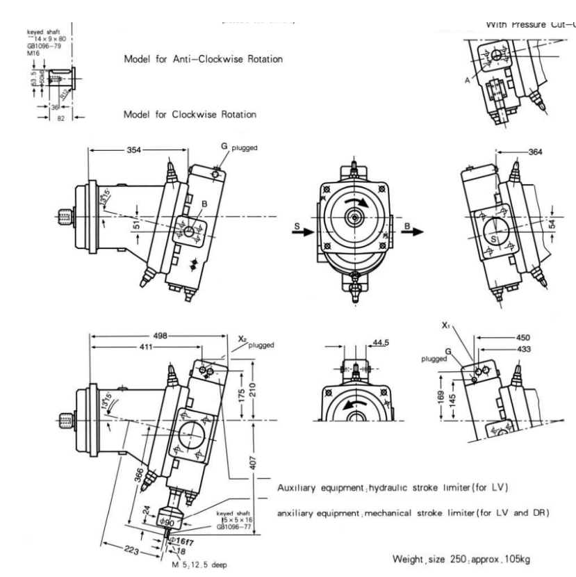
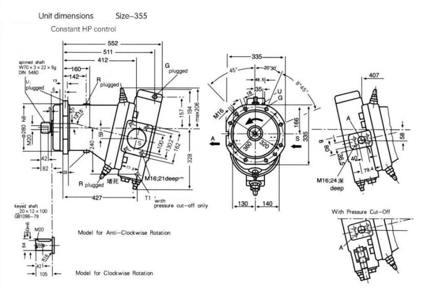
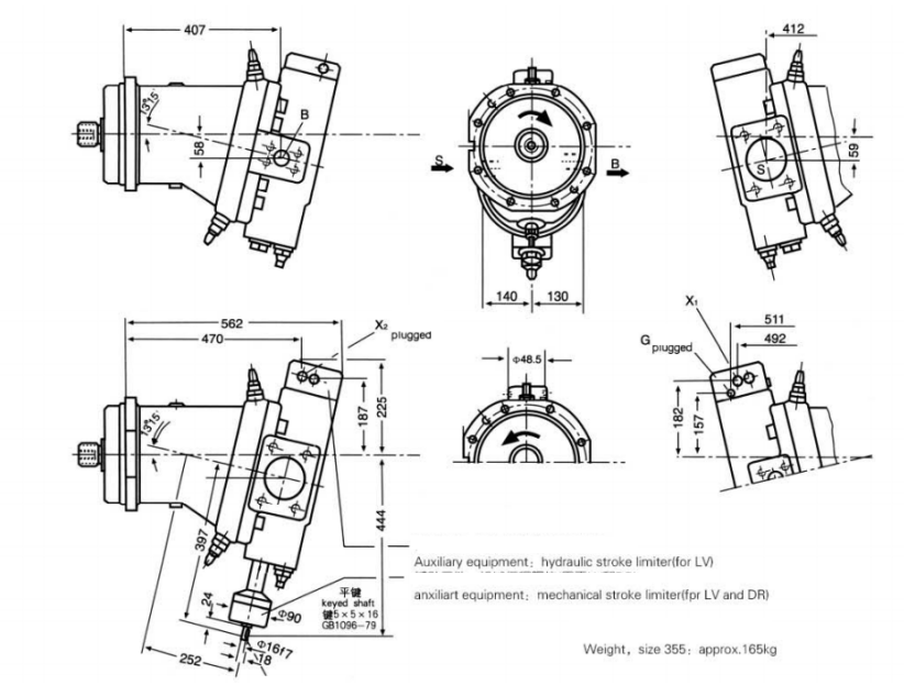
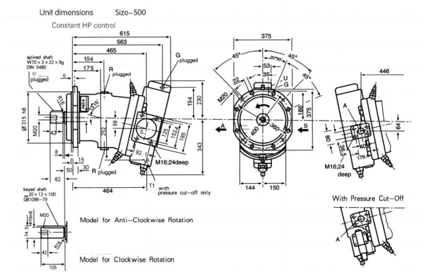
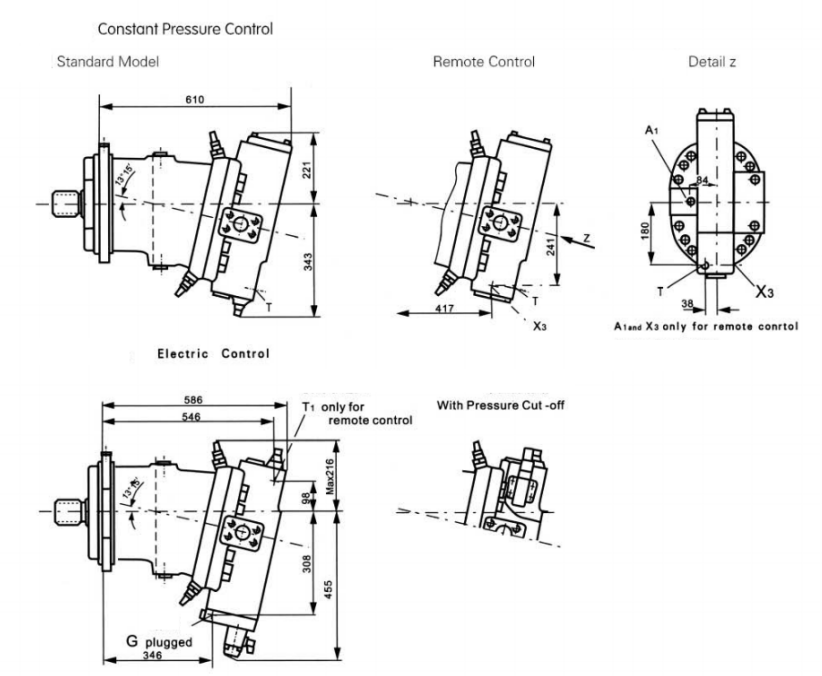
Unit dimensions size 20-160 Constant HP control