中文
中文 English
 Español
 Français
{{i.title_en}}
Axial Piston Fixed Pump HD-A2FM
MOQ: 100 PCS
Note: If you have any questions,please contact us
- 1.Sizes 5~500; Series 6 ; Nominal pressure 400 bar ; Maximum pressure 450 bar
- 2.Fixed motor with axial tapered piston rotary group of bentaxis design, for hydrostatic drives in open and closed circuits
- 3.For use in mobile and stationary applications, The output speed is dependent on the flow of the pump and the displacement of the motor.
- 4.Finely graduated sizes permit far-reaching adaptation to the drive case
- 5.High power density,Small dimensions,High total efficiency, Good starting characteristics,Economical design
- HD-A2FM
BEIJING HUADE HYDRAULIC INDUSTRIAL GROUP CO.,LTD
Since:
1979
Product Description
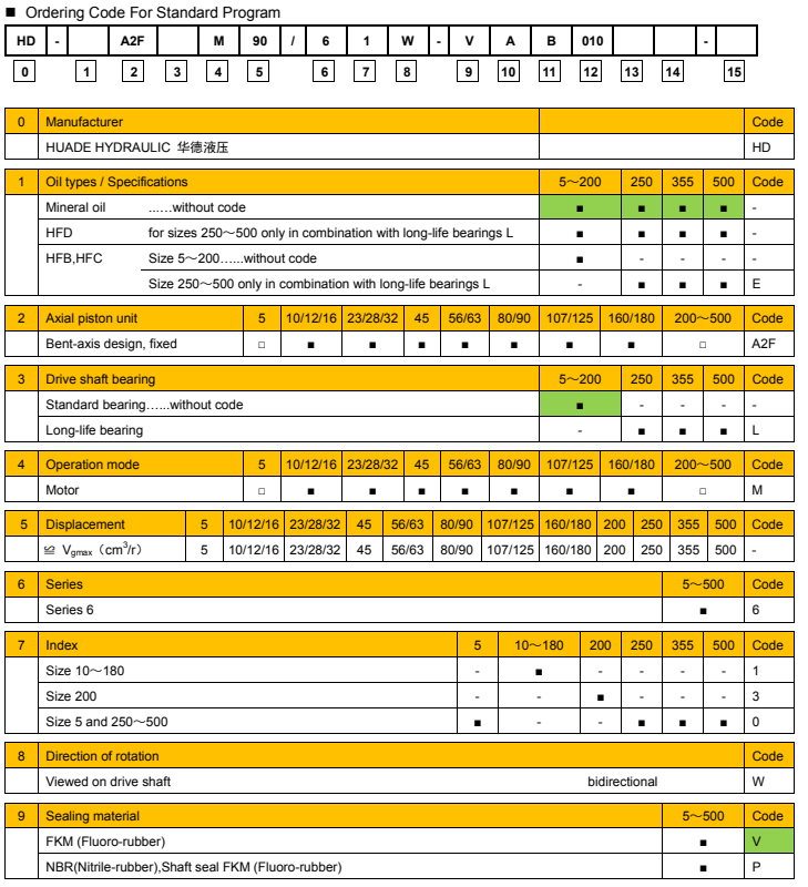
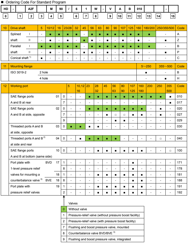
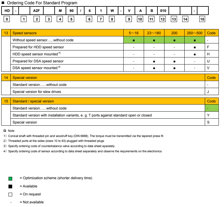
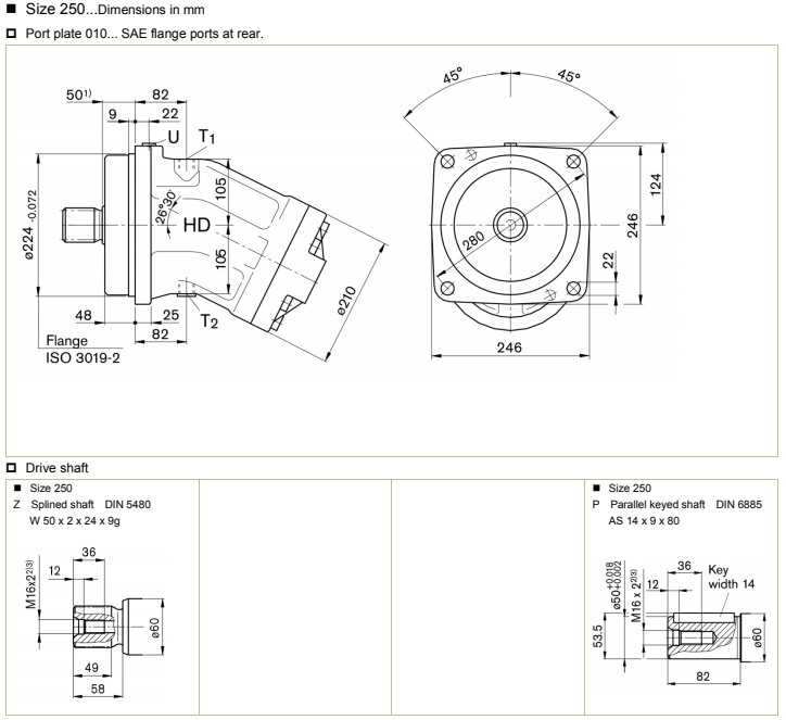
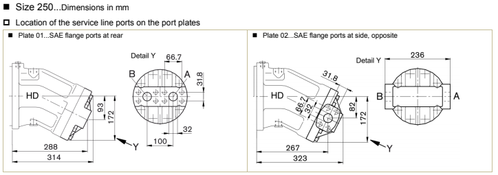
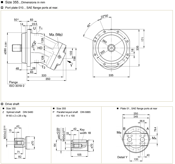
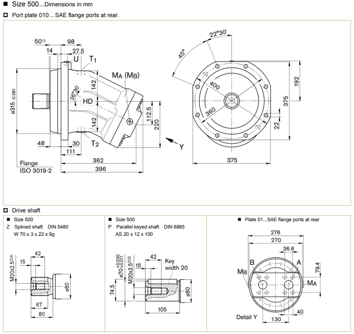
HD-A2FM Axial Piston Fixed Motor Ordering Code
HD-A2FM Axial Piston Fixed Motor Technical Data
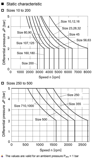
Shaft seal…Permissible pressure loading
The service life of the shaft seal is influenced by the speed of the axial piston unit and the case drain pressure (case pressure).
The mean differential pressure of 2 bar between the case and the ambient pressure may not be enduringly exceeded at normal
operating temperature.
For a higher differential pressure at reduced speed, see diagram.
Momentary pressure spikes (t < 0.1 s) of up to 10 bar are permitted. The service life of the shaft seal decreases with an
increase in the frequency of pressure spikes.
The case pressure must be equal to or higher than the ambient pressure.
Temperature range
The FKM shaft seal may be used for case drain temperatures from -25 °C to +115 °C
For application cases below -25 °C, an NBR shaft seal is required (permissible temperature range -40 °C to +90 °C). State NBR
shaft seal in plain text when ordering. Please contact us.
Direction of flow
| Direction of rotation, viewed on drive shaft | Direction of flow |
| clockwise (R) | A → B |
| counter-clockwise (L) | B → A |
| Sizes | 250 | 355 | 500 |
| qv flush (l/min) | 10 | 16 | 16 |
| Ports | Port for | Diagram |
A, B T | Working port Drain port |
|

| Port for | Standard 6) | Size 3) | P Max [bar] 4) | State 7) | |
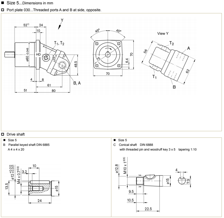
| A , B | Working port | DIN 3852 | M18 x 1.5 deep 12 | 350 | O |
| T 1 | Drain port | DIN 3852 | M10 x 1 deep 8 | 3 | O |
| T 2 | Drain port | DIN 3852 | M10 x 1 deep 8 | 3 | O |
![]()
![]() Note
Note
1) To shaft colla
2) Center bore according to DIN 332 (thread according to DIN 13)
3) For the maximum tightening torques the general instructions must be observed .
4)Momentary pressure spikes may occur depending on the application. Keep this in mind when selecting measuring devices and fittings.
5) Thread according to DIN 3852, maximum tightening torque 30 Nm
6) The spot face can be deeper than specified in the appropriate standard
7) O = Must be connected (plugged on delivery)
| Ports | Port for | Standard | Size 3) | P Max [bar] 4) | State 8) |
| A , B | Working port | see port plates | 450 | ||
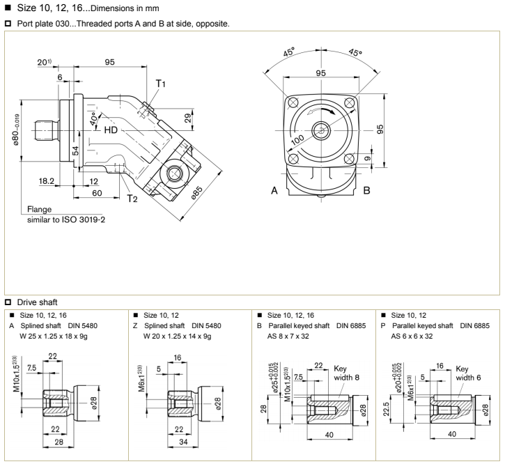
| T 1 | Drain port | DIN 3852 5) | M12 x 1.5 deep 12 | 3 | X 7) |
| T 2 | Drain port | DIN 3852 5) | M12 x 1.5 deep 12 | 3 | O 7) |
![]()
![]()
![]() Note
Note
1) To shaft colla
2) Center bore according to DIN 332 (thread according to DIN 13)
3) For the maximum tightening torques the general instructions must be observed .
4) Momentary pressure spikes may occur depending on the application. Keep this in mind when selecting measuring devices and fittings.
5) The spot face can be deeper than specified in the appropriate standard
7) Depending on the installation position, T1 or T2 must be connected
O = Must be connected (plugged on delivery) X = plugged (in normal operation)
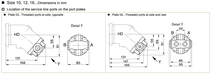
| Plate | Ports | Port for | Standard | Size 1) | P Max [bar] 2) | State 5) |
| 03 | A , B | Working port | DIN 3852 3) | M22 x 1.5 deep 14 | 450 | X |
| 04 | A , B | Working port | DIN 3852 3) | M22 x 1.5 deep 14 | 450 | O |
![]()
![]() Note
Note
1) For the maximum tightening torques the general instructions must be observed .
2) Momentary pressure spikes may occur depending on the application. Keep this in mind when selecting measuring devices and fittings.
3) The spot face can be deeper than specified in the appropriate standard
5) O = Must be connected (plugged on delivery) X = plugged (in normal operation)
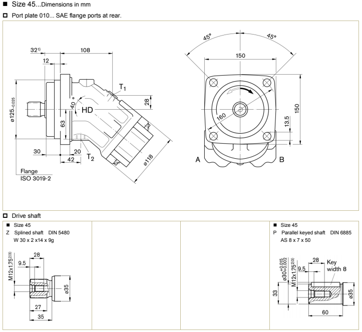
| Ports | Port for | Standard | Size 3) | P Max [bar] 4) | State 8) |
| A , B | Working port | see port plates | 450 | ||
| T 1 | Drain port | DIN 3852 5) | M16 x 1.5 deep 12 | 3 | X 7) |
| T 2 | Drain port | DIN 3852 5) | M16 x 1.5 deep 12 | 3 | O 7) |
![]()
![]()
![]() Note
Note
1) To shaft colla
2) Center bore according to DIN 332 (thread according to DIN 13)
3) For the maximum tightening torques the general instructions must be observed .
4) Momentary pressure spikes may occur depending on the application. Keep this in mind when selecting measuring devices and fittings.
5) The spot face can be deeper than specified in the appropriate standard
7) Depending on the installation position, T1 or T2 must be connected
8) O = Must be connected (plugged on delivery) X = plugged (in normal operation)
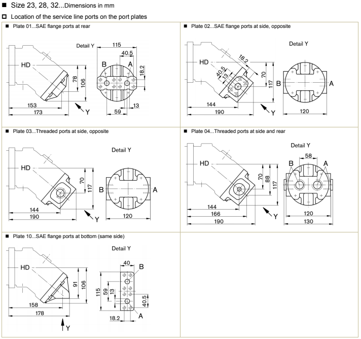
| Plate | Ports | Port for | Standard | Size 1) | P Max [bar] 2) | State 5) |
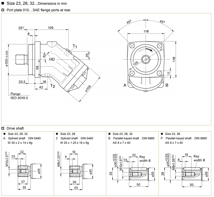
| 01, 02, 10 | A , B | Working port Fastening thread | SAE J518 4) DIN 13 | 1/2” M8 x 1.25 deep 15 | 450 | O |
| 03 | A , B | Working port | DIN 3852 3) | M27 x 2 deep 16 | 450 | X |
| 04 | A , B | Working port | DIN 3852 3) | M27 x 2 deep 16 | 450 | O |
Note
1) For the maximum tightening torques the general instructions must be observed .
2) Momentary pressure spikes may occur depending on the application. Keep this in mind when selecting measuring devices and fittings.
3) The spot face can be deeper than specified in the appropriate standard
4) Only dimensions according to SAE J518, metric fastening thread is a deviation from standard.
5) O = Must be connected (plugged on delivery) X = plugged (in normal operation)
![]()
![]()
![]() Note
Note
1) To shaft colla
2) Center bore according to DIN 332 (thread according to DIN 13)
3) For the maximum tightening torques the general instructions must be observed .
4) Momentary pressure spikes may occur depending on the application. Keep this in mind when selecting measuring devices and fittings.
5) The spot face can be deeper than specified in the appropriate standard
7) Depending on the installation position, T1 or T2 must be connected
8) O = Must be connected (plugged on delivery) X = plugged (in normal operation)
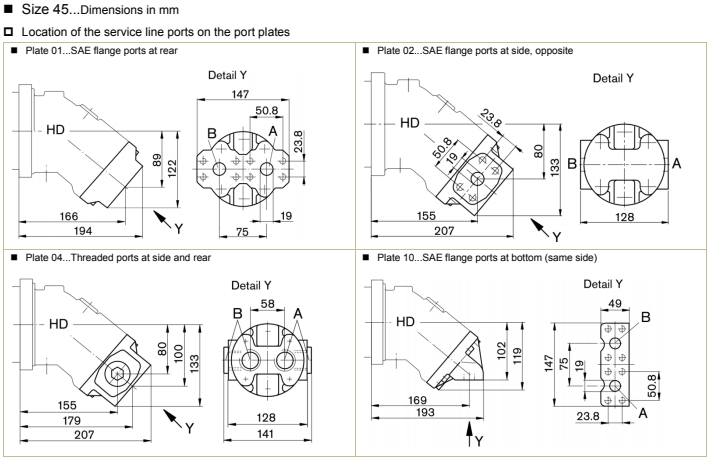
| Plate | Ports | Port for | Standard | Size 1) | P Max [bar] 2) | State 5) |
| 01, 02, 10 | A , B | Working port Fastening thread | SAE J518 4) DIN 13 | 3/4” M10 x 1.5 deep 17 | 450 | O |
| 04 | A , B | Working port | DIN 3852 3) | M33 x 2 deep 18 | 450 | O |
Note
1) For the maximum tightening torques the general instructions must be observed .
2) Momentary pressure spikes may occur depending on the application. Keep this in mind when selecting measuring devices and fittings.
3) The spot face can be deeper than specified in the appropriate standard
4) Only dimensions according to SAE J518, metric fastening thread is a deviation from standard.
5) O = Must be connected (plugged on delivery) X = plugged (in normal operation)
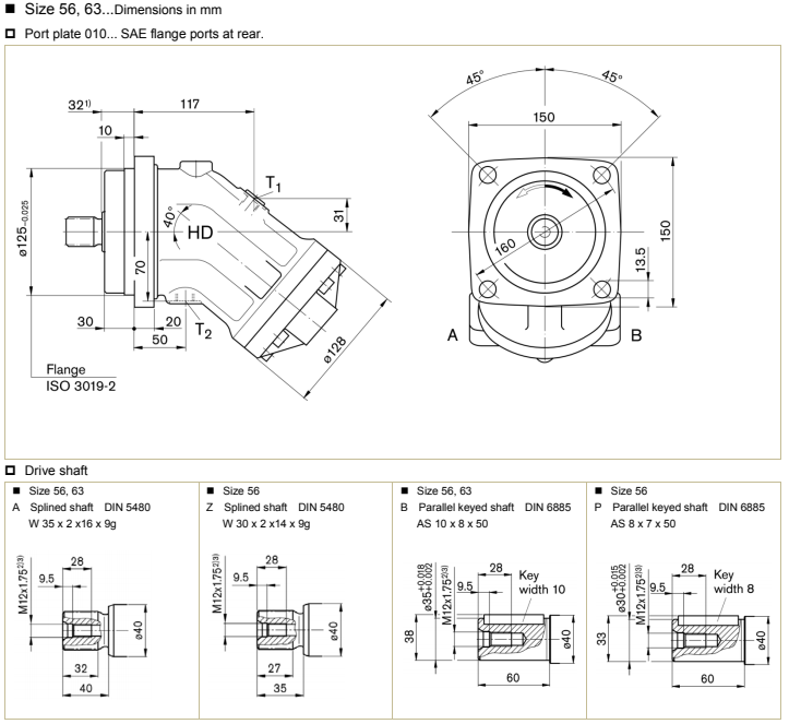
| Ports | Port for | Standard | Size 3) | P Max [bar] 4) | State 8) |
| A , B | Working port | see port plates | 450 | ||
| T 1 | Drain port | DIN 3852 5) | M18 x 1.5 deep 12 | 3 | X 7) |
| T 2 | Drain port | DIN 3852 5) | M18 x 1.5 deep 12 | 3 | O 7) |
![]()
![]()
![]() Note
Note
1) To shaft colla
2) Center bore according to DIN 332 (thread according to DIN 13)
3) For the maximum tightening torques the general instructions must be observed .
4) Momentary pressure spikes may occur depending on the application. Keep this in mind when selecting measuring devices and fittings.
5) The spot face can be deeper than specified in the appropriate standard
7) Depending on the installation position, T1 or T2 must be connected
8) O = Must be connected (plugged on delivery) X = plugged (in normal operation)
| Plate | Ports | Port for | Standard | Size 1) | P Max [bar] 2) | State 5) |
| 01, 02, 10 | A , B | Working port Fastening thread | SAE J518 4) DIN 13 | 3/4” M10 x 1.5 deep 17 | 450 | O |
| 04 | A , B | Working port | DIN 3852 3) | M33 x 2 deep 18 | 450 | O |
Note
1) For the maximum tightening torques the general instructions must be observed .
2) Momentary pressure spikes may occur depending on the application. Keep this in mind when selecting measuring devices and fittings.
3) The spot face can be deeper than specified in the appropriate standard
4) Only dimensions according to SAE J518, metric fastening thread is a deviation from standard.
5) O = Must be connected (plugged on delivery) X = plugged (in normal operation)
| Ports | Port for | Standard | Size 3) | P Max [bar] 4) | State 8) |
| A , B | Working port | see port plates | 450 | ||
| T 1 | Drain port | DIN 3852 5) | M18 x 1.5 deep 12 | 3 | X 7) |
| T 2 | Drain port | DIN 3852 5) | M18 x 1.5 deep 12 | 3 | O 7) |
Note
1) To shaft colla
2) Center bore according to DIN 332 (thread according to DIN 13)
3) For the maximum tightening torques the general instructions must be observed .
4) Momentary pressure spikes may occur depending on the application. Keep this in mind when selecting measuring devices and fittings.
5) The spot face can be deeper than specified in the appropriate standard
7) Depending on the installation position, T1 or T2 must be connected
8) O = Must be connected (plugged on delivery) X = plugged (in normal operation)
| Plate | Ports | Port for | Standard | Size 1) | P Max [bar] 2) | State 5) |
| 01, 02, 10 | A , B | Working port Fastening thread | SAE J518 4) DIN 13 | 3/4” M10 x 1.5 deep 17 | 450 | O |
Note
1) For the maximum tightening torques the general instructions must be observed .
2) Momentary pressure spikes may occur depending on the application. Keep this in mind when selecting measuring devices and fittings.
4) Only dimensions according to SAE J518, metric fastening thread is a deviation from standard.
5) O = Must be connected (plugged on delivery) X = plugged (in normal operation)
| Ports | Port for | Standard | Size 3) | P Max [bar] 4) | State 8) |
| A , B | Working port | see port plates | 450 | ||
| T 1 | Drain port | DIN 3852 5) | M18 x 1.5 deep 12 | 3 | X 7) |
| T 2 | Drain port | DIN 3852 5) | M18 x 1.5 deep 12 | 3 | O 7) |
![]()
![]()
![]() Note
Note
1) To shaft colla
2) Center bore according to DIN 332 (thread according to DIN 13)
3) For the maximum tightening torques the general instructions must be observed .
4) Momentary pressure spikes may occur depending on the application. Keep this in mind when selecting measuring devices and fittings.
5) The spot face can be deeper than specified in the appropriate standard
7) Depending on the installation position, T1 or T2 must be connected
8) O = Must be connected (plugged on delivery) X = plugged (in normal operation)
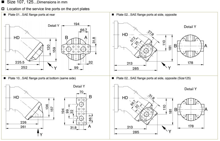
| Plate | Ports | Port for | Standard | Size 1) | P Max [bar] 2) | State 5) |
| 01, 10 | A , B | Working port Fastening thread | SAE J518 4) DIN 13 | 1- 1/4” M14 x 2 deep 19 | 450 | O |
02 Size107 | A , B | Working port Fastening thread | SAE J518 4) DIN 13 | 1” M12 x 1.75 deep 17 | 450 | O |
02 Size125 | A , B | Working port Fastening thread | SAE J518 4) DIN 13 | 1- 1/4” M14 x 2 deep 19 | 450 | O |
Note
1) For the maximum tightening torques the general instructions must be observed .
2) Momentary pressure spikes may occur depending on the application. Keep this in mind when selecting measuring devices and fittings.
4) Only dimensions according to SAE J518, metric fastening thread is a deviation from standard.
5) O = Must be connected (plugged on delivery) X = plugged (in normal operation)
| Ports | Port for | Standard | Size 3) | P Max [bar] 4) | State 8) |
| A , B | Working port | see port plates | 450 | ||
| T 1 | Drain port | DIN 3852 5) | M22 x 1.5 deep 14 | 3 | X 7) |
| T 2 | Drain port | DIN 3852 5) | M22 x 1.5 deep 14 | 3 | O 7) |
![]()
![]()
![]() Note
Note
1) To shaft colla
2) Center bore according to DIN 332 (thread according to DIN 13)
3) For the maximum tightening torques the general instructions must be observed .
4) Momentary pressure spikes may occur depending on the application. Keep this in mind when selecting measuring devices and fittings.
5) The spot face can be deeper than specified in the appropriate standard
7) Depending on the installation position, T1 or T2 must be connected
8) O = Must be connected (plugged on delivery) X = plugged (in normal operation)
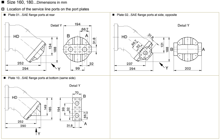
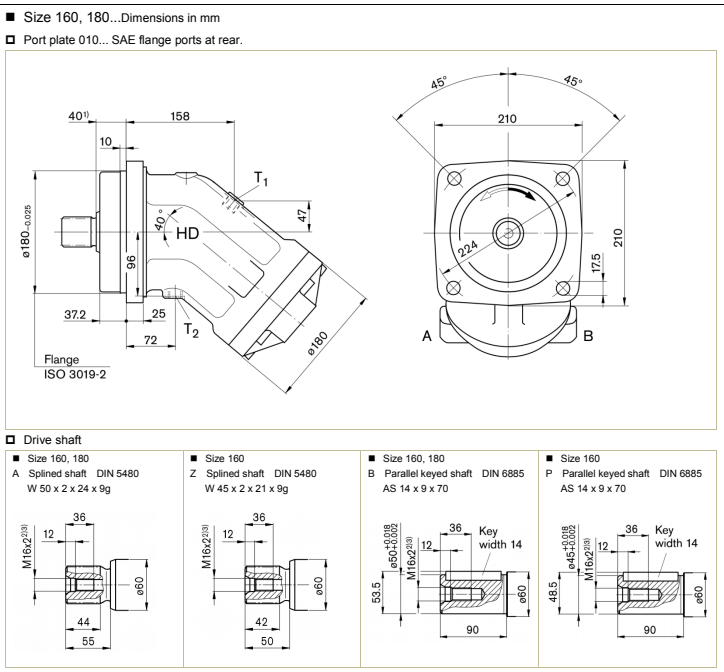
| Plate | Ports | Port for | Standard | Size 1) | P Max [bar] 2) | State 5) |
| 01, 02, 10 | A , B | Working port Fastening thread | SAE J518 4) DIN 13 | 1- 1/4” M14 x 2 deep 19 | 450 | O |
Note
1) For the maximum tightening torques the general instructions must be observed .
2) Momentary pressure spikes may occur depending on the application. Keep this in mind when selecting measuring devices and fittings.
4) Only dimensions according to SAE J518, metric fastening thread is a deviation from standard.
5) O = Must be connected (plugged on delivery) X = plugged (in normal operation)
| Port for | Standard | Size 3) | P Max [bar] 4) | State 8) | |
| A , B | Working port Fastening thread | SAE J518 6) DIN 13 | 1- 1/4” M14 x 2deep 19 | 450 | |
| T 1 | Drain port | DIN 3852 5) | M22 x 1.5 deep 14 | 3 | X 7) |
| T 2 | Drain port | DIN 3852 5) | M22 x 1.5 deep 14 | 3 | O 7) |
Note
1) To shaft colla
2) Center bore according to DIN 332 (thread according to DIN 13)
3) For the maximum tightening torques the general instructions must be observed .
4) Momentary pressure spikes may occur depending on the application. Keep this in mind when selecting measuring devices and fittings.
5) The spot face can be deeper than specified in the appropriate standard
6) Only dimensions according to SAE J518, metric fastening thread is a deviation from standard.
7) Depending on the installation position, T1 or T2 must be connected
8) O = Must be connected (plugged on delivery) X = plugged (in normal operation)
| Ports | Port for | Standard | Size 3) | P Max [bar] 4) | State 8) |
| A , B | Working port | see port plates | 450 | ||
| T 1 | Drain port | DIN 3852 5) | M22 x 1.5 deep 14 | 3 | X 7) |
| T 2 | Drain port | DIN 3852 5) | M22 x 1.5 deep 14 | 3 | O 7) |
| U | Bearing flushing port | DIN 3852 5) | M14 x 1.5 deep 12 | 3 | X |
![]()
![]() Note
Note
1) To shaft colla
2) Center bore according to DIN 332 (thread according to DIN 13)
3) For the maximum tightening torques the general instructions must be observed . 4) Momentary pressure spikes may occur depending on the application. Keep this in mind when selecting measuring devices and fittings.
5) The spot face can be deeper than specified in the appropriate standard
7) Depending on the installation position, T1 or T2 must be connected
8) O = Must be connected (plugged on delivery) X = plugged (in normal operation)
| Plate | Ports | Port for | Standard | Size 1) | P Max [bar] 2) | State 5) |
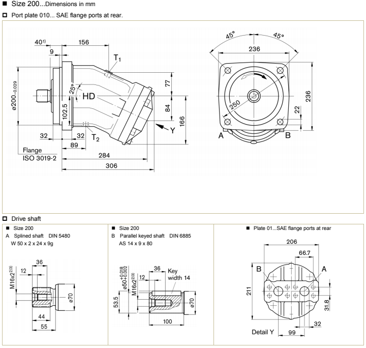
| 01, 02 | A , B | Working port Fastening thread | SAE J518 4) DIN 13 | 1- 1/4” M14 x 2 deep 19 | 400 | O |
Note
1) For the maximum tightening torques the general instructions must be observed .
2) Momentary pressure spikes may occur depending on the application. Keep this in mind when selecting measuring devices and fittings.
4) Only dimensions according to SAE J518, metric fastening thread is a deviation from standard.
5) O = Must be connected (plugged on delivery) X = plugged (in normal operation)
| Ports | Port for | Standard | Size 3) | P Max [bar] 4) | State 8) |
| A , B | Working port Fastening thread | SAE J518 6) DIN 13 | 1- 1/2” M16 x 2 deep 21 | 450 | |
| T 1 | Drain port | DIN 3852 5) | M33 x 2 deep 18 | 3 | X 7) |
| T 2 | Drain port | DIN 3852 5) | M33 x 2 deep 18 | 3 | O 7) |
| U | Bearing flushing port | DIN 3852 5) | M14 x 1.5 deep 12 | 3 | X |
| M A, MB | Measuring workting pressure | DIN 3852 5) | M14 x 1.5 deep 12 | 400 | X |
Note
1) To shaft colla
2) Center bore according to DIN 332 (thread according to DIN 13)
3) For the maximum tightening torques the general instructions must be observed .4) Momentary pressure spikes may occur depending on the application. Keep this in mind when selecting measuring devices and fittings.
5) The spot face can be deeper than specified in the appropriate standard
6) Only dimensions according to SAE J518, metric fastening thread is a deviation from standard.
7) Depending on the installation position, T1 or T2 must be connected
8) O = Must be connected (plugged on delivery) X = plugged (in normal operation)
| Ports | Port for | Standard | Size 3) | P Max [bar] 4) | State 8) |
| A , B | Working port Fastening thread | SAE J518 6) DIN 13 | 1- 1/2” M16 x 2 deep 21 | 450 | |
| T 1 | Drain port | DIN 3852 5) | M33 x 2 deep 18 | 3 | X 7) |
| T 2 | Drain port | DIN 3852 5) | M33 x 2 deep 18 | 3 | O 7) |
| U | Bearing flushing port | DIN 3852 5) | M18 x 1.5 deep 12 | 3 | X |
| M A, MB | Measuring workting pressure | DIN 3852 5) | M14 x 1.5 deep 12 | 400 | X |
Note
1) To shaft colla
2) Center bore according to DIN 332 (thread according to DIN 13)
3) For the maximum tightening torques the general instructions must be observed .
4) Momentary pressure spikes may occur depending on the application. Keep this in mind when selecting measuring devices and fittings.
5) The spot face can be deeper than specified in the appropriate standard
6) Only dimensions according to SAE J518, metric fastening thread is a deviation from standard.
7) Depending on the installation position, T1 or T2 must be connected
8) O = Must be connected (plugged on delivery) X = plugged (in normal operation)
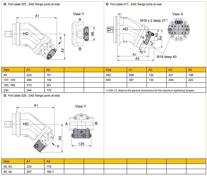
HD-A2FM Axial Piston Fixed Motor Attachment
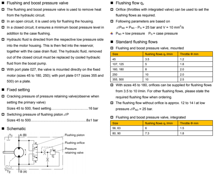
Flushing and boost pressure valve dimensions in mm
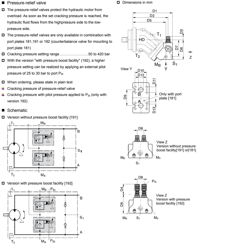
Pressure-relief valve dimensions in mm
| Size | Code | D1 | D2 | D3 | D4 | D5 | D6 | D7 | D8 | D9 | D10 | D11 | D12 | D132) |
| 28 , 32 | MHDB16 | 209 | 186 | 25 | 68 | 174 | 102 | 87 | 36 | 66 | 50.8 | 23.8 | Φ19 | M10 deep 17 |
| 45 | MHDB16 | 222 | 198 | 22 | 65 | 187 | 113 | 98 | 36 | 66 | 50.8 | 23.8 | Φ19 | M10 deep 17 |
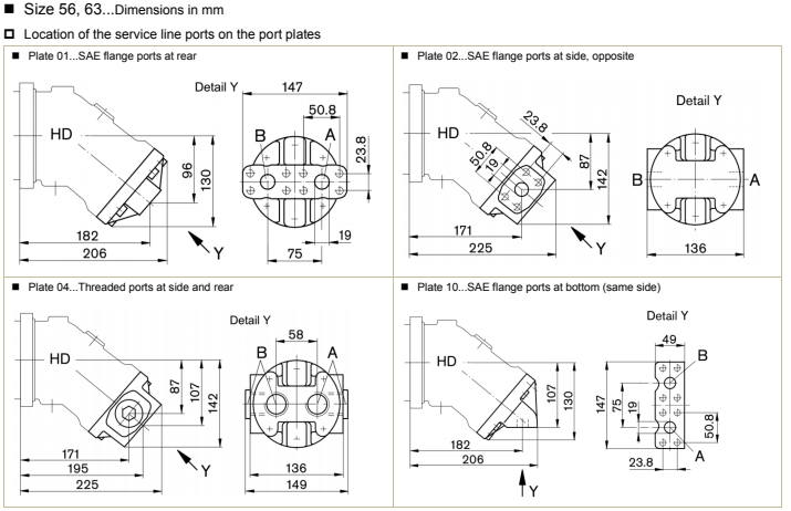
| 56 , 63 | MHDB22 | 250 | 222 | 19 | 61 | 208 | 124 | 105 | 42 | 75 | 50.8 | 23.8 | Φ19 | M10 deep 13 |
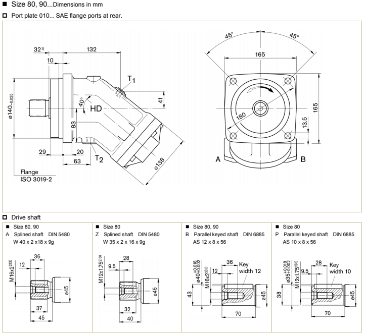
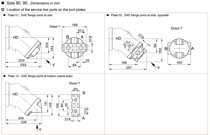
| 80 , 90 | MHDB22 | 271 | 243 | 17.5 | 59 | 229 | 134 | 114 | 42 | 75 | 57.2 | 27.8 | Φ25 | M12 deep 18 |
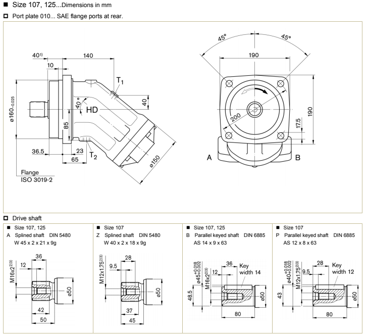
| 107 , 125 | MHDB32 | 298 | 266 | 10 | 52 | 250 | 149.5 | 130 | 53 | 84 | 66.7 | 31.8 | Φ32 | M14 deep 19 |
| 160 , 180 | MHDB32 | 332 | 301 | 5 | 47 | 285 | 170 | 149 | 53 | 84 | 66.7 | 31.8 | Φ32 | M14 deep 19 |
| Size | Port A ,B | S11) | M A, M B1) | P St1) | |
| 28 , 32 | 3/4” | M22 x 1.5 deep 14 | M20 x 1.5 deep 14 | G1/4” | Assembly instructions for port plate with pressure boost facility "192"The lock nut must be counterheld when installing the hydraulic line at the pst port |
| 45 | 3/4” | M22 x 1.5 deep 14 | M20 x 1.5 deep 14 | G1/4” | |
| 56 , 63 | 3/4” | M26 x 1.5 deep 16 | M26 x 1.5 deep 16 | G1/4” | |
| 80 , 90 | 1” | M26 x 1.5 deep 16 | M26 x 1.5 deep 16 | G1/4” | |
| 107 , 125 | 1- 1/4” | M26 x 1.5 deep 16 | M26 x 1.5 deep 16 | G1/4” | |
| 160 , 180 | 1- 1/4” | M26 x 1.5 deep 16 | M30 x 1.5 deep 16 | G1/4” |
| Ports | Port for | Standard | Size 1) | P Max [bar] 2) | State 3) |
| A , B | Working port | SAE J518 | See above | 450 | O |
| S1 | Supply port (only with port plate 191/192) | DIN 3852 | See above | 5 | O |
| M A, M B | Measuring operating pressure port | DIN 3852 | See above | 450 | X |
| P St | Pilot pressure port (only with port plate 192) | DIN 3852 | See above | 30 | O |
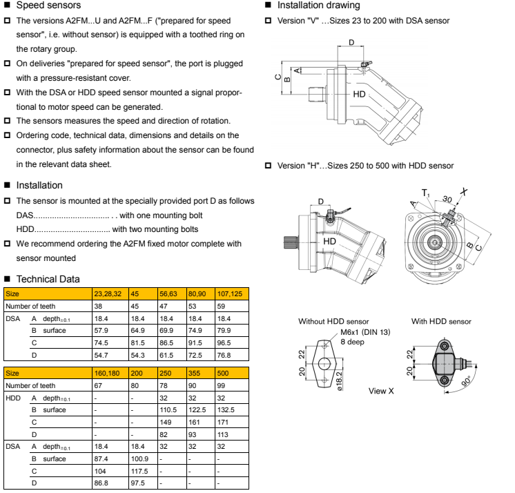
Counterbalance valve BVD and BVE
Travel drive/winch counterbalance valves are designed to reduce the danger of overspeeding and cavitation of axial piston motors in open circuits.
Cavitation occurs if the motor speed is greater than it should be for the given input flow while braking, travelling downhill, or lowering a load.
If the inlet pressure drops, the counterbalance spool throttles the return flow and brakes the motor until the inlet pressure returns to approx. 20 bar
BVD available for sizes 28 to 180 and BVE available for sizes 107 to 180.
The counterbalance valve must be ordered additionally. We recommend ordering the counterbalance valve and the motor as a set.
Note
Ordering example
A2FM90/61W–VAB188 + BVD20F27S/41B–V03K16D0400S12
The counterbalance valve does not replace the mechanical service brake and park brake.
Observe the detailed notes on the BVD counterbalance valve and BVE counterbalance valve
For the design of the brake release valve, we must know for the mechanical park brake the pressure at the start of opening
The volume of the counterbalance spool between minimum stroke (brake closed) and maximum stroke (brake released with 21 bar)
The required closing time for a warm device (oil viscosity approx 15 mm2/s)
Technical Data
Permissible input flow or pressure in operation with DBV and BVD/BE
| Motor | Without valve | Restricted values in operation with DBV | Restricted values in operation with BVD/BVE | |||||||
| HD-A2FM | Pnom/Pmax | qv max | DBV | Pnom/Pmax | qv max | Plate | BVD/BVE | Pnom/Pmax | qv max | Plate |
| Size | bar | l/min | size | bar | l/min | Code | size | bar | I/min | Code |
| 28 | 400/450 | 176 | 16 | 350/420 | 100 | 181 191 , 192 | 20 BVD | 350/420 | 100 | 188 |
| 32 | 201 | |||||||||
| 45 | 255 | |||||||||
| 56 | 280 | 22 | 240 | 220 | ||||||
| 63 | 315 | |||||||||
| 80 | 360 | |||||||||
| 90 | 405 | |||||||||
| 107 | 427 | 171 ,191 , 192 | 178 | |||||||
| 125 | 500 | |||||||||
| 107 | 427 | 32 | 400 | 181,191 , 192 | 25 BVD/BVE | 320 | 188 | |||
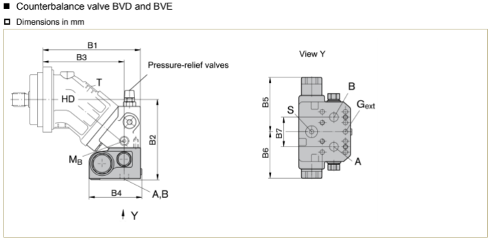
| HD-A2FM | Counterbalance valve | Dimensions in mm | ||||||||
| Size | Type | Port A, B | B1 | B2 | B3 | B4(S) | B4(L) | B5 | B6 | B7 |
| 28 , 32 | BVD20 … 16 | 3/4” | 209 | 175 | 174 | 142 | 147 | 139 | 98 | 66 |
| 45 | BVD20 … 16 | 3/4” | 222 | 196 | 187 | 142 | 147 | 139 | 98 | 66 |
| 56 , 63 | BVD20 … 17 | 3/4” | 250 | 197 | 208 | 142 | 147 | 139 | 98 | 75 |
| 80 , 90 | BVD20 …27 | 1” | 271 | 207 | 229 | 142 | 147 | 139 | 98 | 75 |
| 107 , 125 | BVD20 …28 | 1” | 298 | 238 | 251 | 142 | 147 | 139 | 98 | 84 |
| 107 , 125 | BVD25 …38 | 1- 1/4” | 298 | 239 | 251 | 158 | 163 | 175 | 120.5 | 84 |
| 160 , 180 | BVD25 …38 | 1- 1/4” | 332 | 260 | 285 | 158 | 163 | 175 | 120.5 | 84 |
| 107 , 125 | BVE25 … 38 | 1- 1/4” | 298 | 240 | 251 | 167 | 172 | 214 | 137 | 84 |
| 160 , 180 | BVE25 … 38 | 1- 1/4” | 332 | 260 | 285 | 167 | 172 | 214 | 137 | 84 |
| 250 | On request | |||||||||
| Ports | Port for Version | Standard | Size 1) | P Max [bar] 2) | State4) |
| A , B | Working port | SAE J518 | See above | 420 | O |
| S | BVD20,BVD25, BVE25 | DIN 3852 3) | M22 x 1.5 deep 14 | 30 | X |
| DIN 3852 3) | M27 x 2 deep 16 | 30 | X | ||
| Br | Brake release,reduce high pressure L | DIN 3852 3) | M12 x 1.5 deep 12.5 | 30 | O |
| Gext | Brake release,high pressure S | DIN 3852 3) | M12 x 1.5 deep 12.5 | 420 | X |
| M A, MB | Measuring pressure A, B | ISO 6149 3) | M12 x 1.5 deep 12 | 420 | X |
Note
1) For the maximum tightening torques the general instructions must be observed .
2) Momentary pressure spikes may occur depending on the application. Keep this in mind when selecting measuring devices and fittings.
3) The spot face can be deeper than specified in the appropriate standard
4) O = Must be connected (plugged on delivery) X = plugged (in normal operation)
Technical Information
Hydraulic fluid
Before starting project planning, please refer to our data sheets mineral oil and environmentally acceptable hydraulic fluids for detailed information regarding the choice of hydraulic fluid and application conditions.
When using environmentally acceptable hydraulic fluids, the limitations regarding technical data and seals must be observed.
Please contact us. When ordering, indicate the hydraulic fluid that is to be used.
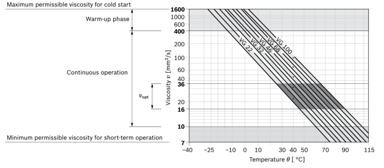
Notes on the choice of hydraulic fluid
In order to select the correct hydraulic fluid, it is necessary to know the operating temperature in the reservoir (open circuit) in relation to the ambient temperature.
The hydraulic fluid should be selected so that within the operating temperature range, the viscosity lies within the optimum range (nopt), see shaded section of the selection diagram. We recommend to select the higher viscosity grade in each case.
Example: at an ambient temperature of X ℃ the operating temperature is 60℃. In the optimum operating viscosity range (Vopt; shaded area) this corresponds to viscosity grades VG 46 resp. VG 68; VG 68 should be selected.
Important
The case drain temperature is influenced by pressure and input speed and is always higher than the reservoir temperature.
However, at no point in the component may the temperature exceed 90℃. The temperature difference specified on the left is to be taken into account when determining the viscosity in the bearing
If the above conditions cannot be met, due to extreme operating parameters please contact us.
Filtration of the hydraulic fluid
The finer the filtration the better the cleanliness level of the hydraulic fluid and the longer the service life of the axial piston unit.
In order to guarantee the functional reliability of the axial piston unit it is necessary to carry out a gravimetric evaluation of the hydraulic fluid to determine the particle contamination and the cleanliness level according to ISO 4406.
A cleanliness level of at least 20/18/15 must be maintained.
At very high hydraulic fluid temperatures (90℃ to maximum 115℃), a cleanliness level of at least 19/17/14 according to ISO 4406 is necessary.
If the above cleanliness levels cannot be maintained, contact us.
Viscosity and temperature of hydraulic fluids
| Viscosity | Shaft seal | Temperature 3) | Comment | |
| Cold start | Vmax ≤1600 mm2/s | NBR 2) FKM | θSt ≥ -40℃ θSt ≥ -25℃ | t ≤3 min, without load (P ≤ 50 bar) n≤1000 rpm Permissible temperature difference between axial piston unit and hydraulic fluid in the system maximum 25 K |
| Warm-up phase | V = 1600~400 mm2/s | t ≤15 min,P ≤0.7*P nom and n ≤ 0.5*n nom | ||
Continuous operation | V = 400~10 mm2/s1) | NBR 2) FKM | θ= +85℃ T = +110℃ | measured at port L, L1 |
| V = 36~16 mm2/s | Range of optimum operating viscosity and efciency | |||
Short-term operation | V = 10~7 mm2/s | NBR 2) FKM | θ = +85℃ θ = +110℃ | t ≤3 min,P ≤0.3*P nom measured at port L, L1 |
1)Corresponds e.g. for VG 46 to a temperature range of +4 °C to +85 °C (see selection diagram)
2)Version EA10VSO...-P (if operating with HFA, HFB and HFC hydraulic fluids)
3)If the temperature at extreme operating parameters cannot be adhered to, please contact us
Selection diagram
General instructions
The pump HD-A2FO is designed to be used in open circuits. The motor HD-A2FM/E is designed to be used in open and closedcircuits.
The project planning, installation and commissioning of the axial piston unit requires the involvement of qualified personnel.
Before using the axial piston unit, please read the corresponding instruction manual completely and thoroughly.
During and shortly after operation, there is a risk of burns on the axial piston unit. Take appropriate safety measures (e.g. by wearing protective clothing).
Depending on the operating conditions of the axial piston unit (operating pressure, fluid temperature), the characteristic may shift.
Service line ports
The ports and fastening threads are designed for the specified maximum pressure.
The machine or system manufacturer must ensure that the connecting elements and lines correspond to the specified application conditions (pressure, flow, hydraulic fluid, temperature) with the necessary safety factors.
The service line ports and function ports can only be used to accommodate hydraulic lines.
The data and notes contained herein must be adhered to.
The product is not approved as a component for the safety concept of a general machine according to ISO 13849.
The following tightening torques apply
Fittings
Observe the manufacturer's instructions regarding tightening torques of the fittings used
Mounting bolts
For mounting bolts with metric ISO thread according to DIN 13 or with thread according to ASME B1.1, we recommend checking the tightening torque in individual cases in accordance with VDI 2230.
Female threads in the axial piston unit
The maximum permissible tightening torques MG max are maximum values for the female threads and must not be exceeded. For values, see the following table.
Threaded plugs
For the metallic threaded plugs supplied with the axial piston unit, the required tightening torques of threaded plugs MV apply. For values, see the following table.
| Ports | Maximum permissible tightening torque of the female threads M Gmax | Required tightening torque of the threaded plugs Mv1) | hexagon socket in the threaded plugs WAF | |
| Standard | Size of thread | |||
| DIN 3852 | M8 x 1 | 10 Nm | 7 Nm | 3 mm |
| M10 x 1 | 30 Nm | 12 Nm | 5 mm | |
| M12 x 1.5 | 50 Nm | 25 Nm 2) | 6 mm | |
| M14 x 1.5 | 80 Nm | 35 Nm | 6 mm | |
| M16 x 1.5 | 100 Nm | 50 Nm | 8 mm | |
| M18 x 1.5 | 140 Nm | 60 Nm | 8 mm | |
| M22 x 1.5 | 210 Nm | 80 Nm | 10 mm | |
| M26 x 1.5 | 230 Nm | 120 Nm | 12 mm | |
| M27 x 2 | 330 Nm | 135 Nm | 12 mm | |
| M33 x 2 | 540 Nm | 225 Nm | 17 mm | |
| M42 x 2 | 720 Nm | 360 Nm | 22 mm | |
| DIN ISO 228 | G1/4” | 40 Nm | - | - |
Note
1) The tightening torques apply for screws in the "dry" state as received on delivery and in the "lightly oiled" state for installation.
2) In the "lightly oiled" state, the MV is reduced to 10 Nm for M10 x 1 and 17 Nm for M12 x 1.5.